|
 |
|
SUITABLE MODELS FLYING YOUR MODEL All champion flyers fly their Fox motor with the needle valve set sufficiently rich so that the model four cycles (misfires every other revolution) while the model is in level flight. When the model is pulled into a climb or a loop or other maneuver, the motor starts firing every revolution, giving the model the extra power it needs at that time. This is a feature that has enabled the Fox motor to win more stunt contests than all other makes combined during the past 30 years. It is a mistake to lean the motor in before flight so that it is running at full power. Fox motors are fit very closely and care should be taken to not fly them overlean at any time. No special break in other than careful flying is required. |
|
WARNING Never fly a control line model within 200 feet of power lines. Death by electrocution is possible if your model comes near power lines. Direct contact is not necessary. |
|
WARNING There is always the possibility that you may lose control of your model. Do not fly in any location where your model might strike people or do property damage should this occur. |
|
WARNING A model airplane motor can get hot enough to cause a serious burn. Do not touch the motor right after it has been running. |
|
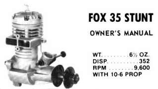
INSTALLATION Fox motors should be mounted in the most rigid manner possible. If hardwood beams are used they should be well braced at the firewall with hardwood crosspieces and a strong, fuel resistant glue such as epoxy should be used. If a firewall mount is used the firewall should be secured to the fuselage sides in such a way that it cannot flex. An overly flexible mount will allow the motor to vibrate excessively, cause poor running, and eventually tear the airplane apart. Unbalanced props will do this too. Location of the fuel tank is very important in a stunt model in order that the motor speed will remain fairly constant throughout the maneuvers. The ideal location is close in back of the motor setting on the motor mounts. The fuel line to be used is a medium size neoprene or silicone. The fuel tank to be used for built up models is a Fox 1-3/4" wide square wedge tank of suitable length. For profile type models either Fox profile tank works fine. If the motor is cowled, provision should be made for the cool air to circulate past the crankcase as well as past the cylinder fins, as a considerable amount of heat is dissipated there. Free flight models should have the top of the tank about the same height as the needle valve. PROPELLER-FUEL-GLOW PLUGS Experience has shown that the Fox 35 Stunt motor performs best with these accessories: Fox Superfuel,, Fox long glow plugs, and a 10-6 propeller. We would like to call your attention to the fact that Fox Superfuel contains more oil than other commercial brands, and the Fox 35 seems to require this oil content for dependable operation and long life. If you feel compelled to use another brand of fuel, we strongly recommend that you add castor oil to it to bring the total oil content up to 28 percent. |
|
WARNING Always keep clear of the propeller. It is possible for a propeller to cut a finger off, or for a piece to come off and put out an eye. |
|
WARNING Model airplane fuel is both flammable and extremely poisonous. Use the same safety precautions you would with a can of gasoline or bottle of poison. |
|
CLEANING THE MOTOR A motor loaded with dirt can be cleaned as follows: IN CASE OF CRASH The design of a Fox motor is simple and straightforward. Most repairs you can make yourself by replacing the damaged parts. In case your dealer does not care to supply you the parts, you may get them directly from the factory. DISASSEMBLY The unnecessary disassembling of a motor is not recommended. When a motor is disassembled and reassembled there is little chance of getting every microscopic groove and ridge in the piston and cylinder to match as before, therefore, they must wear in again. This results in harder starting and a loss of power. If it does become necessary to disassemble the motor, proceed as follows: 1. Rotate the crankshaft until the piston is at bottom
dead center. To reassemble the motor, reverse this procedure, replacing all screws and gaskets. |
| PARTS LIST | ||
| Crankcase | 13501 | 11.50 |
| Cylinder Head | 13502 | 6.50 |
| Cylinder and Piston | 13504 | 13.00 |
| Wrist Pin | 13506 | 1.00 |
| Wrist Pin Keepers | 13540 | 1.00 |
| Connecting Rod | 13507 | 8.00 |
| Crankshaft | 13508 | 11.00 |
| Clockwise Crankshaft | 13528 | 13.00 |
| Thrust Washer | 13509 | 2.00 |
| Needle Valve Assembly | 13510 | 3.00 |
| Rear Cover | 13511 | 5.00 |
| Prop Nut | 13512 | 1.25 |
| Prop Washer | 13513 | 1.25 |
| Screw & Gasket Set | 13514 | 1.50 |
| NV Body, Spring & Nut | 13532 | 2.00 |
| Needle Only | 13516 | 1.50 |
| 8-32 Hex Nuts (pkg of 3) | 22570 | 1.00 |